60 Second Timer

In this project, the task was to create a counter that goes from 0-59 that continues from 0 once it reaches 59. We had to use one synchronous counter, and one asynchronous, as well as build in a reset that will reset it to 0.
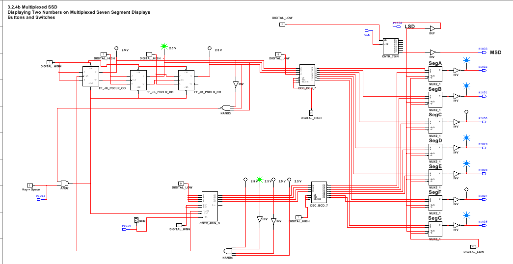
PLD Circuit
Conclusion
In this project, we had to use both synchronous and asynchronous counters. the difference between the two is that with synchronous counters, all the flip flops are connected to the clock. Asynchronous counters work by the first flip flop is connected to the clock, but each successive flip flop is connected to an output ( Q or notQ) from the previous flip flop. two MSI chips that work as binary counters are the 74LS193 chip and the 74LS163 chip. '163 is the MSI synchronous counter, and '193 is the asynchronous.
In terms of building this circuit, the project went fairly smoothly. Working in PLD mode, I first copied and pasted the multiplexer aspect of the project from the link on Ms. Zienty’s website. Next, I began on the One’s column of my timer. I Used the PLD equivalent of a 74LS163 chip, and connected the outputs to the multiplexer inputs. For the inputs on the ‘163, I connected them all to a digital low, as this is what we want the counter to clear to once it reaches 9. To detect a 9, I used inverters and a 4-input NAND gate and created a binary equivalent of 9 using the outputs from the ‘163 chip. This NAND chip is connected to the clear of the ‘163 chip, as well as the clock of the ten’s column. The tens’ column is wired so the notQ runs into the next CLK, making it an asynchronous up-counter. Each J/K for the 3 Ten’s column flip flops and its presets are connected to a digital high, making the data in toggle and and the presets inactive. Since we need the timer to stop at 59, there is no need for a 4th flip flop, as it doesn’t ever get past 7 (the most digits 3 flip flops can display). The Q’s of the flip flops are connected to the Multiplexer, with the last D input connected to a digital low since its not needed. To make the timer stop at 59 and reset at 0, the Clears are connected to an and gate which is connected to a switch and a 3-input NAND that detects a 6, which will cause the 10’s section to clear once it detects a 6, which will never be displayed due to how asynchronous counters work. This switch is important as if turned off, it will reset the counter to 0. While everyone in class had pretty much the same circuit design, not everyone’s worked once downloaded on to the PLD chip. I have no idea why, all I know is that I hate PLD chips and think they should be eradicated from the face of the earth.
In terms of building this circuit, the project went fairly smoothly. Working in PLD mode, I first copied and pasted the multiplexer aspect of the project from the link on Ms. Zienty’s website. Next, I began on the One’s column of my timer. I Used the PLD equivalent of a 74LS163 chip, and connected the outputs to the multiplexer inputs. For the inputs on the ‘163, I connected them all to a digital low, as this is what we want the counter to clear to once it reaches 9. To detect a 9, I used inverters and a 4-input NAND gate and created a binary equivalent of 9 using the outputs from the ‘163 chip. This NAND chip is connected to the clear of the ‘163 chip, as well as the clock of the ten’s column. The tens’ column is wired so the notQ runs into the next CLK, making it an asynchronous up-counter. Each J/K for the 3 Ten’s column flip flops and its presets are connected to a digital high, making the data in toggle and and the presets inactive. Since we need the timer to stop at 59, there is no need for a 4th flip flop, as it doesn’t ever get past 7 (the most digits 3 flip flops can display). The Q’s of the flip flops are connected to the Multiplexer, with the last D input connected to a digital low since its not needed. To make the timer stop at 59 and reset at 0, the Clears are connected to an and gate which is connected to a switch and a 3-input NAND that detects a 6, which will cause the 10’s section to clear once it detects a 6, which will never be displayed due to how asynchronous counters work. This switch is important as if turned off, it will reset the counter to 0. While everyone in class had pretty much the same circuit design, not everyone’s worked once downloaded on to the PLD chip. I have no idea why, all I know is that I hate PLD chips and think they should be eradicated from the face of the earth.
