Date of Birth Poject

The purpose of this project was to work with a 7- segment display to show your birthday, using 3 switches. Using a common cathode 7-segment display, I created a truth table, extracted a simplified logic expression using Karnaugh Maps, created a Multisim using my logic expressions and NAND-logic, and created the circuit using a breadboard and many wires.
Truth Table
To figure out which switches needed to be on to create each number in my birthday, i created a truth table to extract logic expressions i would need to implement my circuit correctly.

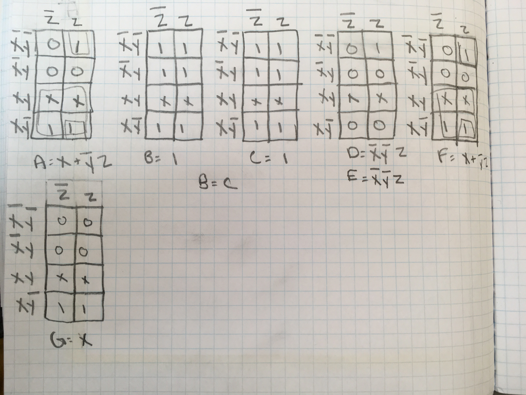
Karnaugh Maps
Karnaugh maps are used to simplify truth tables and the expressions that come out of them, without using the cursed boolean algebra. In K-mapping, you create a table that is based off of how many switches you have in your truth table. In this case, I had 3 variables, and therefore needed 8 spaces in my K-maps. For A, B, C, D, E, F, and G (each segment in the 7- Segment Display), there is a K-Map with 8 Spaces, and every combination of the variables is shown. Grouping the terms together on the map in groups of 4, and using the Pac-man Method by combining two or more terms on opposite sides of the K-Map, i was able to find all of the simplified expressions needed to create my Birthday. The expressions that are created when done correctly and fully simplified and in SOP form.
MultiSim Implementation
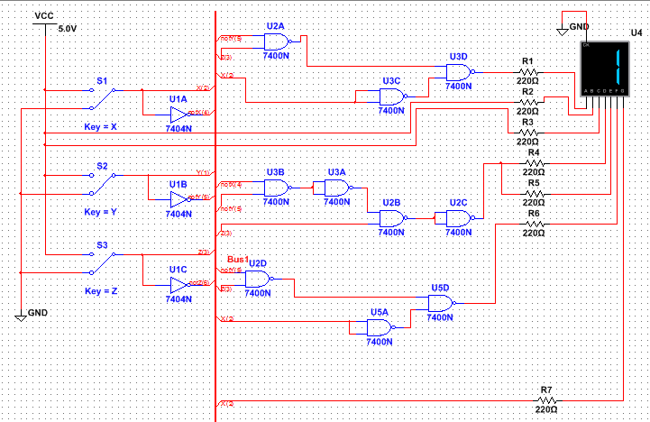
This circuit was implemented using only two different types of gates, NAND and Inverters (I'm aware i could just substitute out the Invertor for more NAND chips, but this was the least confusing way for me to implement my circuit). Using only NAND chips and Inverters is efficient and easier to bread-board, which is why i did so on my MultiSim implementation. using this NAND implementation decreases the number of chips needed and the variety of chips, which is more efficient than AOI logic. For each unique segment on the 7-Segment Display, which are labeled A-G, an expression and circuit are created for them to be turned on when they are supposed to. The segment is turned on when the circuit outputs a High or One feeding into that Segment. Luckily, i had to only create 3 different circuits, as i had recurring 1's, 0's, and 9's in my Birthday (10/11/99).
Bill of Materials
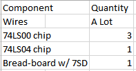
This list of materials shows what was needed to breadboard my circuit. The amount of wires needed may never be known, it was just a lot.
Bread-boarding
This bread-boarding experience went just as smoothly as the last. My abilities allowed me to not have to troubleshoot, and color-coding the wires helped me more than i thought it would. I oriented my chips with the 74LS04 first, with the 3 74LS00's following that one, which was the easiest way to create the circuits considering many started with NOT terms, and the 04 chip is the closest to the start of the circuits.
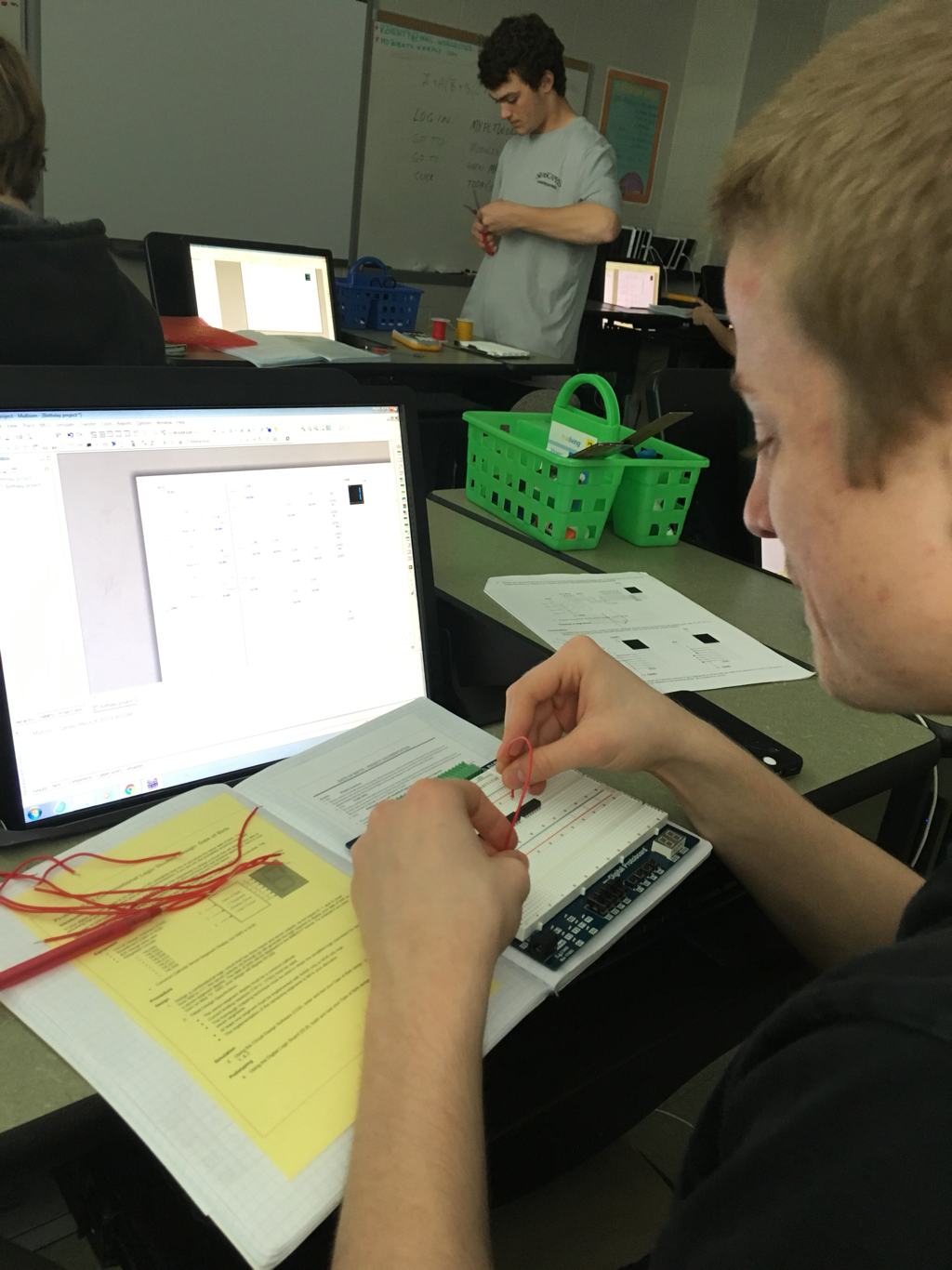
This shows the very start of the bread-boarding process.
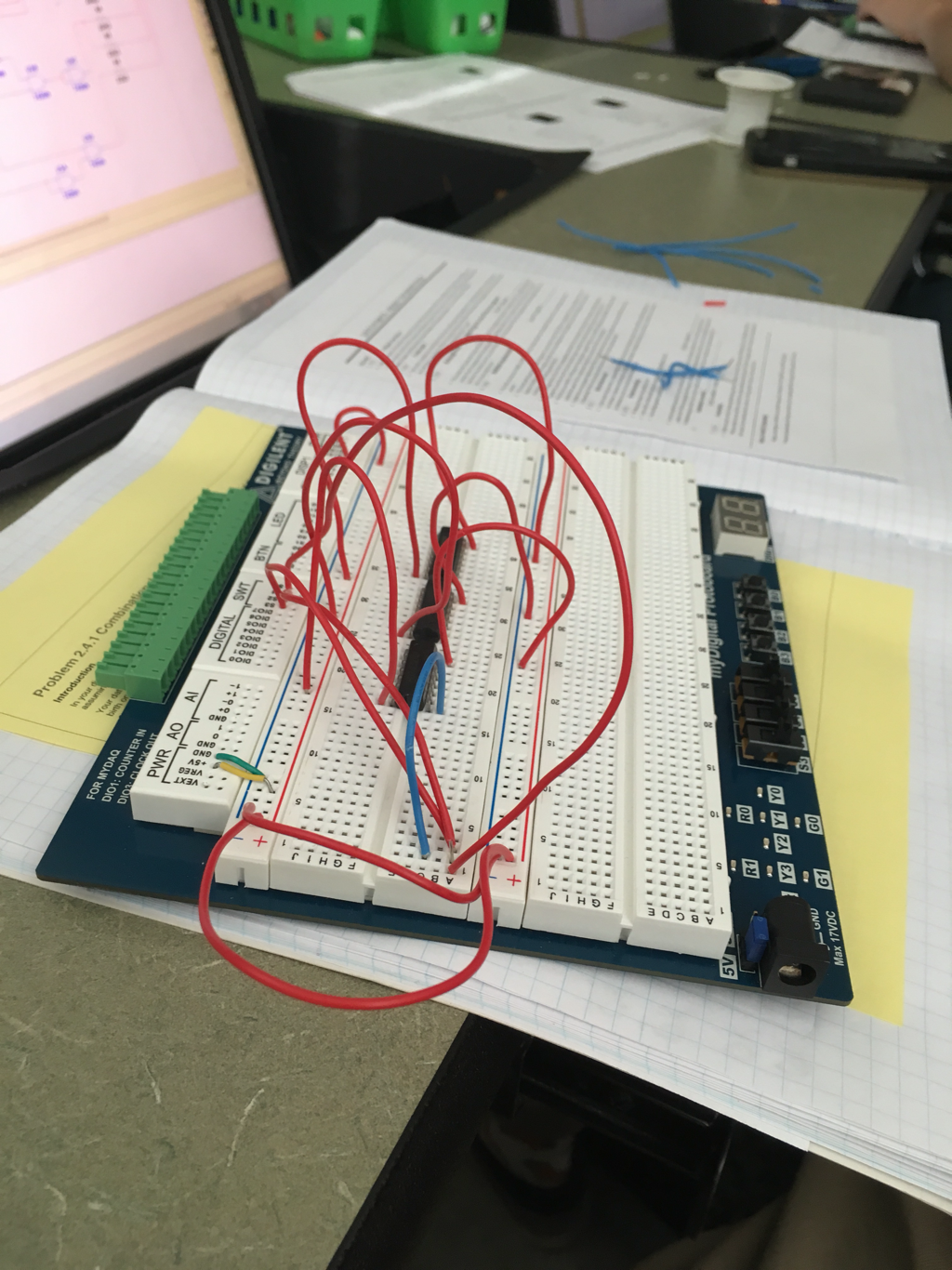
This is a picture of the board with the basic power connections and chips, the circuits not yet implemented.
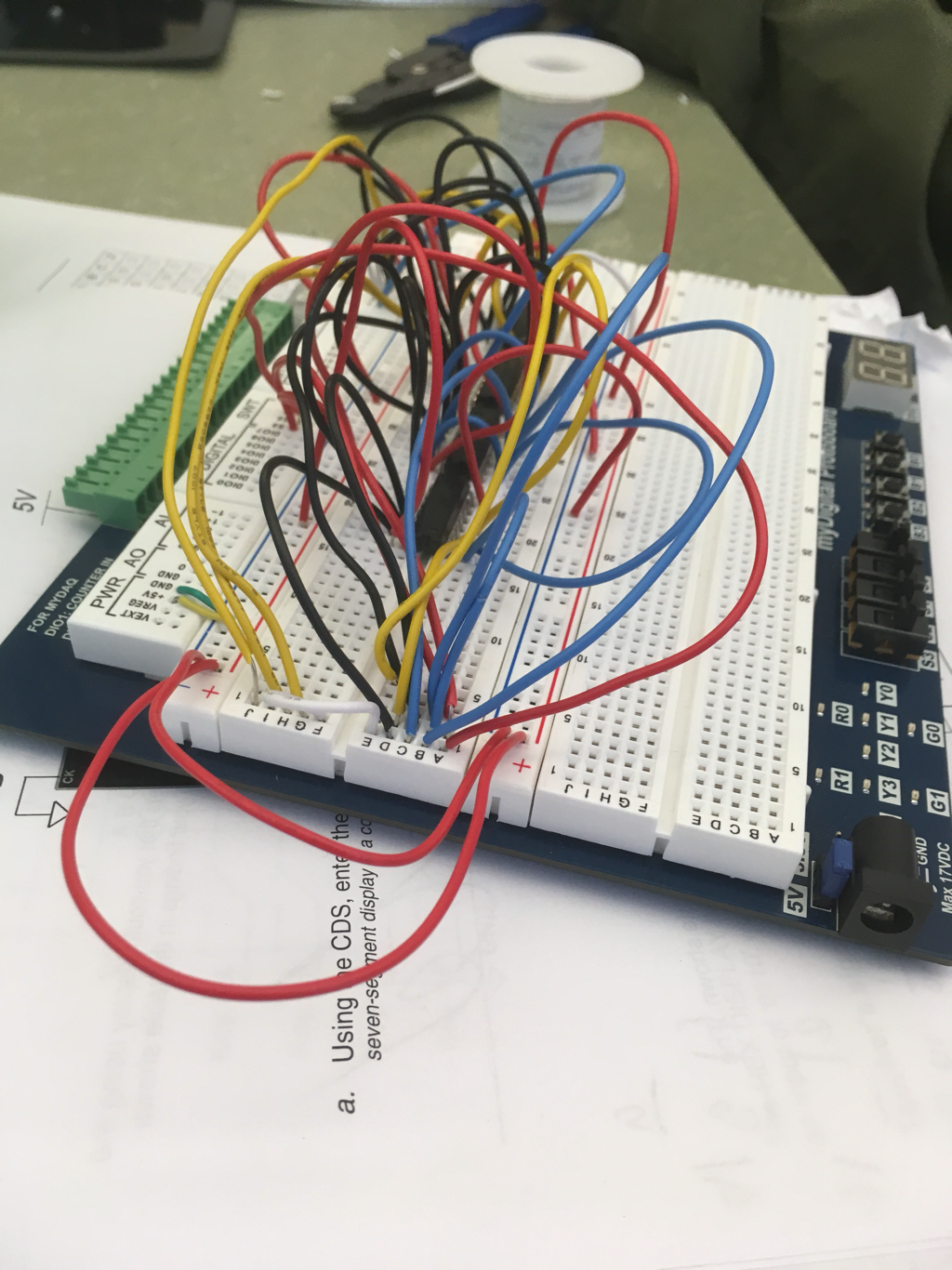
This shows the final completed circuit, which works perfectly. Color-coating the wires per segment made things very easy, although the sheer amount of wires used made things difficult and confusing.
Conclusion
I learned from this project how to use a 7-segment display, and to come up with all the logic to do so (truth table, K-mapping, MultiSim, and Bread-boarding), as we havent done any work with them before. all in all, it was not more difficult to do than a normal circuit, just slightly more work and it took some comprehension, which was easy with our wonderful teacher. While I started behind, i worked quickly, and really only struggled with the initial truth table. After that, everything was very easy. I really enjoyed the process of K-mapping, as it eliminates the need for boolean algebra, aka the devil. it is much easier and less time consuming, and therefore very efficient. the MultiSim work and Bread-boarding were very easy, as once again i am bread-boarding god.
