
|
Project OverviewThe purpose of this project was to create logic expressions, truth tables, and AOI logic circuits for a vote including candidates for President, Vice President, Secretary, and Treasurer. the Outcomes were either pass or fail (1-Pass, 0-Fail), depending on majority. Problems that arose were what happens when there is a tie, the constraint of only 2-input components, and creating AOI logic circuits with so many components.
|
Problem Conception

This table allows us to see all the possible outcomes from the election. It accounts for each outcome, as there is 4 variables, there is 2^4 outcomes, which is why there is 16 rows in the truth table. This truth table shows what is needed for a vote to "pass." It also shows what happens when there is a 2-2 vote tie, in which if the president is represented by a 1 (a "yes" vote), then the vote passes and the outcome is 1. If the president is represented by a 0 (a "no" vote), then the vote fails and the outcome is 0.

This is the un-simplified expression for the truth table. For every time D is turned on (has a value of 1), the column associated is put into the expression as a minterm. this expression is in Sum of Products form because when recording a logic expression from a truth table, this is the easiest way to record it, rather than put it into Product of Sums form.
Un-Simplified Circuit
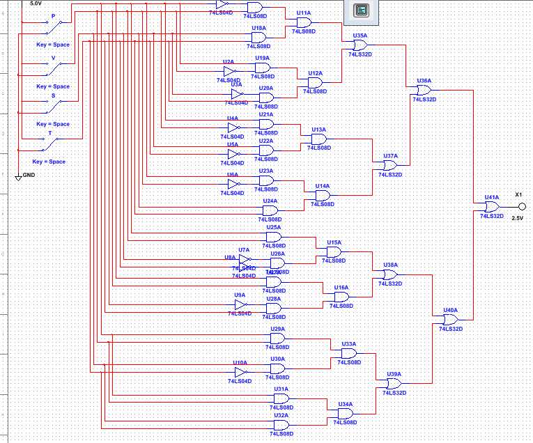
This schematic diagram shows the un-simplified expression shown above in circuit form. I created this by recreating every minterm in the expression, using Inverter, AND, and OR gates. For each minterm, three AND gates were needed; two gates to connect two of the terms, and then one to connect those two AND gates. The amount of inverters changes for each branch of the expression, but in total 10 were used, to represent the NOT's in the expression. A total of 41 gates were used: 10 inverters, 24 AND gates, and 7 OR gates. Therefore, 2 74LS04 chips (Inverter chips), 6 74LS08 chips (AND gates), and 2 74LS32 chips (OR chips) would be needed to create this un-simplified circuit.
Boolean Algebra- Simplified Expression
the diagram and expression above are very long and require a lot of gates, so I used boolean algebra to simplify this expression. the simplified expression is: D=VST+PV+PS+PT. This is how I acquired this expression:

Simplified Circuit
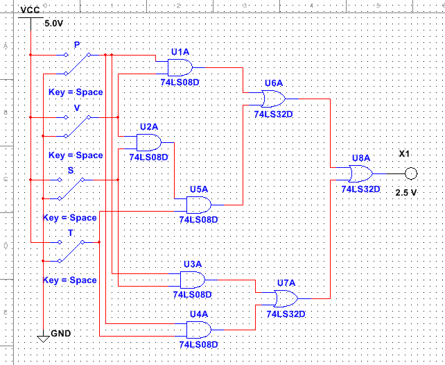
This is the simplified circuit created from the simplified expression shown above. As you can see, this expression is much shorter and uses way less gates, but still brings the same results as the Un-simplified expression. Another interesting thing about this circuit is that is uses no inverter gates, whereas the Un-simplified uses 10. In total, this circuit uses 8 gates: 5 AND gates and 3 OR. For this circuit, only 2 74LS08 chips and 1 74LS32 chip would be needed. While we did not use a resistor at the end of the circuit before the LED, the purpose of one would be to ensure that the bulb does not short out, or too much current passes through it.
Bill of Materials
To create this simplified circuit on a breadboard, these are the materials needed to do so. This list shows the components needed, and the quantity of each component.

Conclusion
This project taught me a lot about Logic expressions and circuit design. This was the first time where I developed my own truth table, logic expression, simplified logic expression, and breadboard showing this. While I did make no mistakes and everything went smoothly from start to finish, creating the original logic expression on Multisim was a tedious and long process. Due to the fact that we were only allowed to use 2-input AND gates and 2-input OR gates, to create the original SOP expression found from the truth table, over 40 components were needed, with many overlapping wires. However, using Boolean algebra, I was able to create a much simpler expression that used not even close to the amount of components needed for the simplified expression. While I’m not the best at Boolean algebra, I was able to, with some help, find the correct simplified expression. With Boolean algebra, engineers are able to significantly reduce the amounts of components needed to recreate the original outcome. The expressions may look different, but yield the same final result. The final aspect of this project was the bread boarding. While some carefully took their time in completing this part of the project, as a mistake means troubleshooting and troubleshooting means tedious wire tracing which is hard and not easy. However, my circuit worked perfectly, and no troubleshooting was needed. All in all, this project taught me a lot about creating your own logic expressions and circuits, and was fun and not too difficult.
