Beginning
During the creation of this project we were asked to create a logic circuit that will detect a paper jam in a copier. We were also asked to implement this design on to a circuit board and create a real life example of our circuit.

Circuits
1. Why Resistors?
Pins 1,2, and 3 are what connect to the Fishertechnik kit phototransistor setup. While breadboarding, resistors were needed that went from the Fishertech kit and the PLD chip. This is so the circuit would not get shorted out by too much voltage.
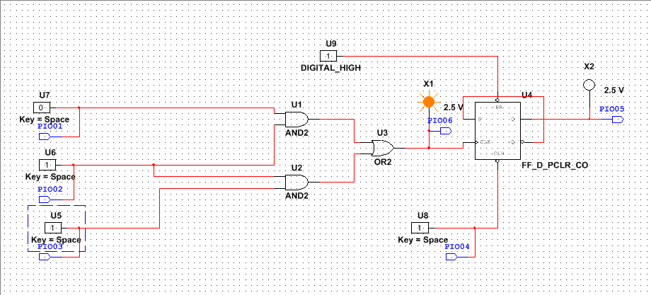
2.What is the purpose of combinational logic circuit?
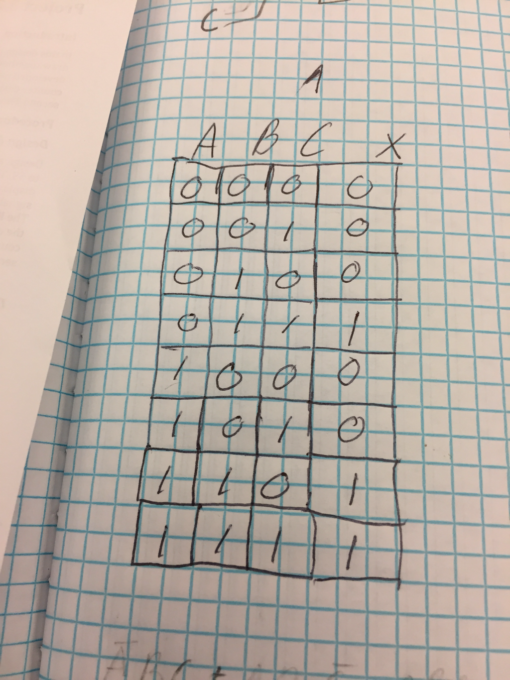
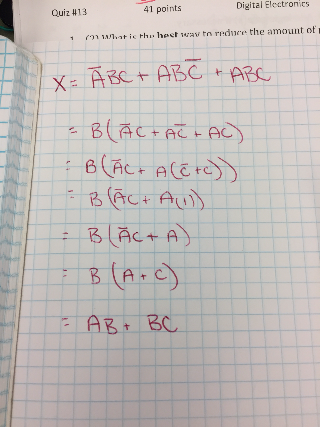
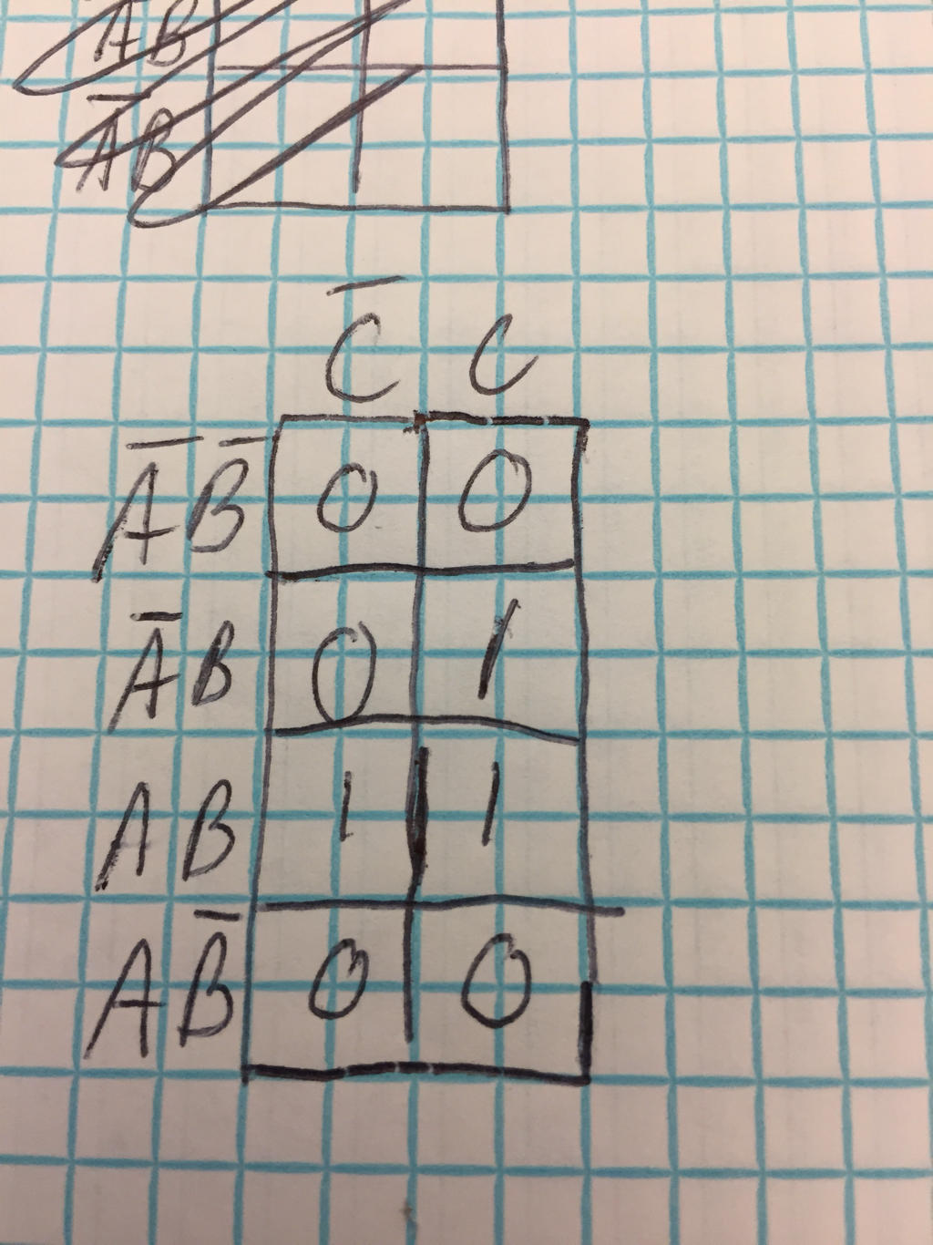
The combinational logic circuit is implemented so the LED and Buzzer go off when they're supposed to. the logic will output a one when two adjacent phototransistors are being blocked by paper ( when 2 adjacent pins output a 1 (supposedly)). This then goes into a clock signal of a D Flip-Flop, which will stay on until cleared.
3. Why do we have a Flip-Flop?
The Flip-Flop is implemented so, after the combinational logic, the signal that goes through goes into the CLK of the Flip-flop, which is set to toggle. However, once a signal goes through, and a 1 is output from the Flip-Flop, it will not turn off until cleared by the CLR. This is for the buzzer, as it is not supposed to stop buzzing until a button (CLR) is reset.
4.Why LED goes off, but buzzer stays on?
The LED is implemented after the combinational logic, but before the Flip-Flop. this means that whenever the logic outputs a 1, the light will be on, and when the logic outputs a 0, the light is off. this differs from the buzzer, which is after the Flip-Flop, in that the buzzer will stay on till cleared.
Pins 1,2, and 3 are what connect to the Fishertechnik kit phototransistor setup. While breadboarding, resistors were needed that went from the Fishertech kit and the PLD chip. This is so the circuit would not get shorted out by too much voltage.
2.What is the purpose of combinational logic circuit?
The combinational logic circuit is implemented so the LED and Buzzer go off when they're supposed to. the logic will output a one when two adjacent phototransistors are being blocked by paper ( when 2 adjacent pins output a 1 (supposedly)). This then goes into a clock signal of a D Flip-Flop, which will stay on until cleared.
3. Why do we have a Flip-Flop?
The Flip-Flop is implemented so, after the combinational logic, the signal that goes through goes into the CLK of the Flip-flop, which is set to toggle. However, once a signal goes through, and a 1 is output from the Flip-Flop, it will not turn off until cleared by the CLR. This is for the buzzer, as it is not supposed to stop buzzing until a button (CLR) is reset.
4.Why LED goes off, but buzzer stays on?
The LED is implemented after the combinational logic, but before the Flip-Flop. this means that whenever the logic outputs a 1, the light will be on, and when the logic outputs a 0, the light is off. this differs from the buzzer, which is after the Flip-Flop, in that the buzzer will stay on till cleared.
