DMV Display
In this project, our task was to create an asynchronous counter. This counter would count up from 0-80, stopping at 80, while being able to reset to 0 at any time. we then had to build the circuit in PLD mode, and show that it worked on the breadboard using the PLD chip and the built-in 7 segment displays of the breadboard.

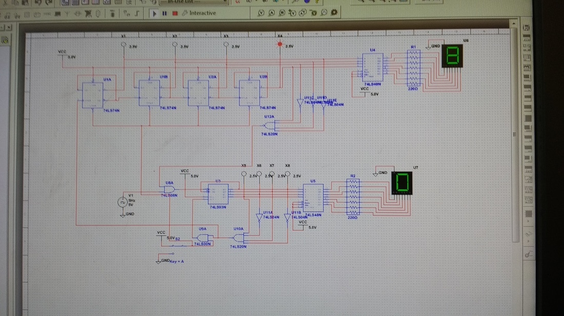
MultiSim circuit
PLD circuit
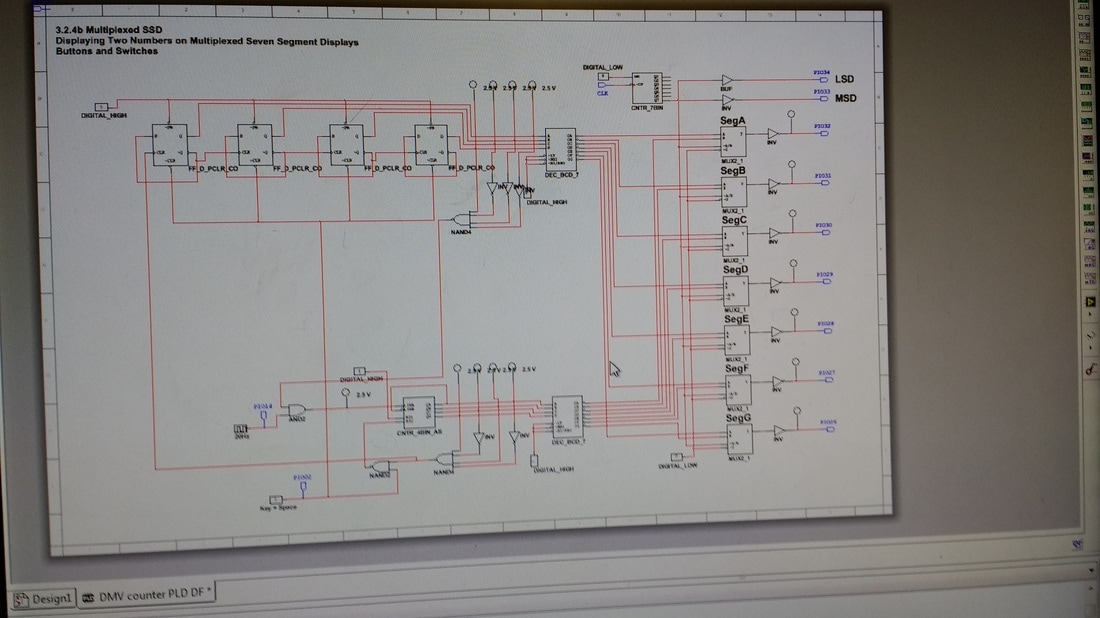
PLD mode is different from the original Multisim mode in that it has pins that correspond to one large chip that is able to have circuits downloaded onto it. This makes it easy to build circuits on a breadboard, as once you are finished designing and pin assigning in PLD mode of Multisim, you are able to upload your circuit straight to the chip and test it by using significantly less wires than breadboarding a normaly design mode circuit. PLD mode has input and output pins and LEDs, which the user (me) can assign to certain switches and lights onto the breadboard. In PLD mode, there are either input or output connectors. Input connectors get assigned some sort of switch or source, such as the clock or switch on the breadboard. Output connectors will be assigned a pin, and from this pin a wire will go to some sort of output on the breadboard, such as the 7-segment display or an LED on the board.
Bill Of Materials
Item Quantity
Breadboard 1
PLD Chip 1
Wires 13
Breadboard 1
PLD Chip 1
Wires 13
Conclusion
The difference between SSI (Small scale intergration) and MSI (medium scale integration) is the number of gates per IC chip there are. an SSI IC chip will have less than 10 gates, while an MSI will have anywhere from 10-100. The circuit I created is an MSI circuit, and its limitations include only being able to count up (a limitation of the 74LS93 chip) and only being able to reset to 0 and hold at 80- so no stopping at a specific number. Because it is an asynchronous counter, it is known as a ripple counter. this is because there i only one clock input, which feeds into the first flip-flop, whose output will be the clock input for the next clock, and so the clock input "ripples" throughout the circuit. The clock input starts in the 1's column/ section of the circuit design. it goes into the 74LS93 chip, which will count from 0-9. Once 10 is detected, (0101 in binary) the 1's counter resets to 0, and a clock pulse is sent into the 10's column/ section of the board, which begins to count upward every time a 10 is reached in the 1's section. the counter stops at 80 because when an 8 is detected in the 10's column, the wiring causes the clock to stop inputting, and the count holds. Key A is a reset key, and if it is switched, the resets in both the 10's and 1's parts of the circuits get activated, or connected to ground, and the counters reset to 0.
